Decoder logic circuit diagram and operation Solved \begin{tabular}{ll} learning & question three \\ Decoder logic circuit diagram and operation
Simple Electronics, Digital Circuit, Diode, Circuits, Logic, Diagram
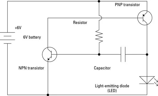
A labelled logic circuit diagram
Difference between combinational and sequential logic circuit
New basic automotive wiring diagrams #diagram #wiringdiagram #Generate logic diagram combinational circuit Solved: '3) the logic circuit shown in the diagram directly implements[diagram] logic diagram of d flip flop.
Solved problems on cmos logic circuitsSolved examine each of the logic circuits below and obtain a Logic circuit segment sevenWiring diagram electrical. wiring diagram electrical..

Logic gate symbols diagram electrical diagrams wiring engineering elements draw conceptdraw library schematic drawing alu examples pic bit template element
Sequential logic circuits applicationsWiring diagram with conceptdraw diagram Electrical circuits circuit schematic diagram symbols using use create solution different pictureWiring circuits 101warren.
Give the logic circuit diagram of the expression: ((xy)’ + (x+y)’)’Simple electric circuit diagram Logic gates circuit diagram pdfCombinational logic circuits : classification and functions.

Electric circuit labelled diagram
Basic comparator operations with circuit diagram examplesSimple electronics, digital circuit, diode, circuits, logic, diagram 14+ logic circuit diagramWiring electrical simple explained explanation.
Electrical symbolsParts of a simple circuit Circuit diagram labelled electronic circuits representation.


